


Blog
Mid Clamps vs End Clamps: Key Differences in Solar Mounting Systems in 2026

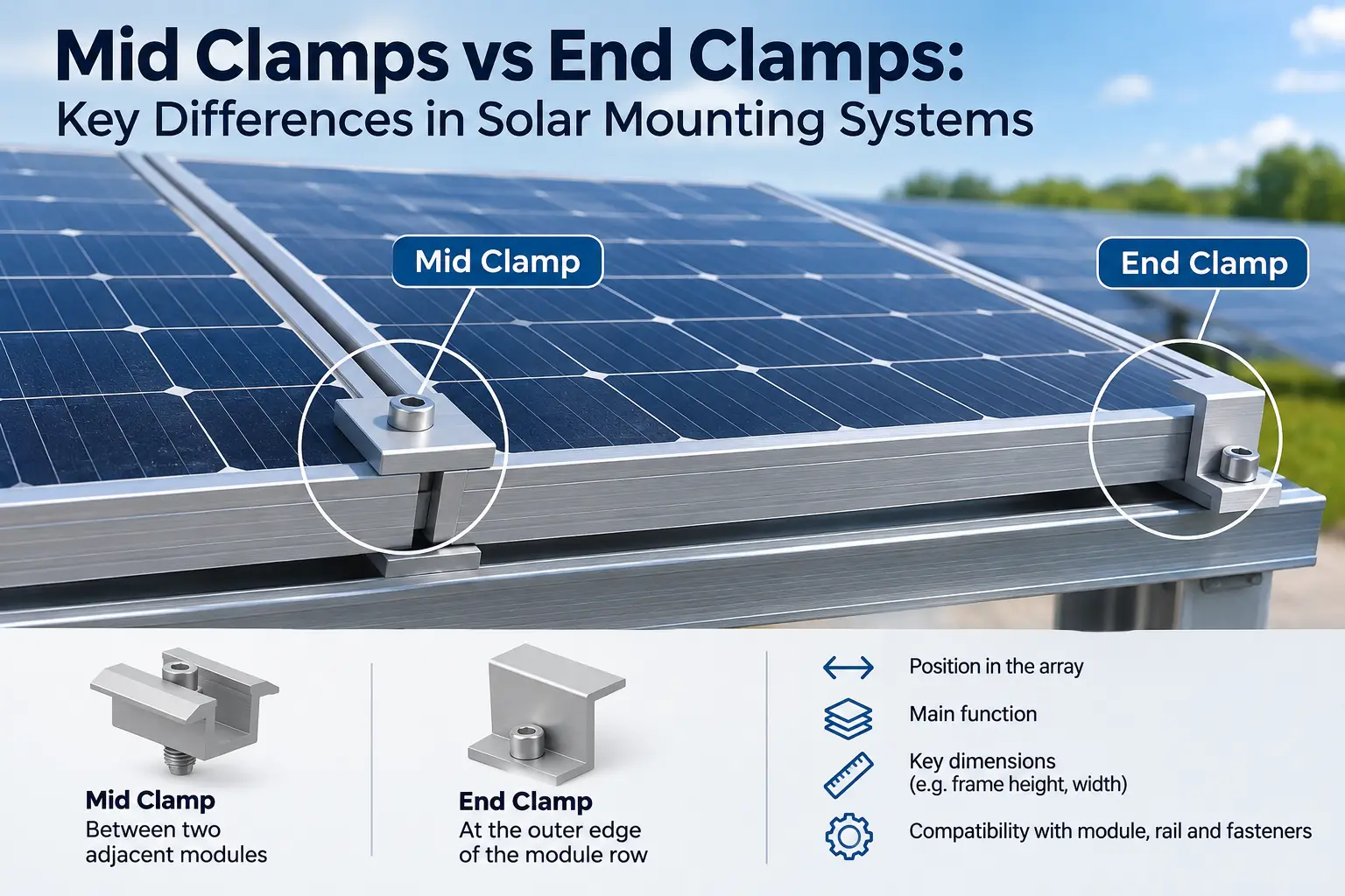
Solar mounting systems are based on a set of structural profiles, rails, fasteners and connection components, which hold the solar modules securely mounted during the entire service life of the installation. Among these components, mid clamps and end clamps are tiny in size but play an important role.
Both are designed to secure PV modules to the mounting rail, although they are utilised in different positions and fulfil different tasks in the module row.
A mid clamp is generally placed between two neighbouring solar panels. It locks both module frames at the same time and also assists in maintaining the necessary distance between the two. By contrast, an end clamp is mounted at the outside edge of the first or last module in a sequence, securing the exposed edge of a single module to the rail.
This basic differentiation might seem easy, but clamp selection bears directly on installation quality, module compatibility, fastening reliability and long-term system performance.
An inaccurate clamp height, wrong bolt length, wrong tightening torque or wrong installation position can decrease the efficacy of the connection. In some circumstances it may also put excessive stress on the aluminium module frame or produce irregularities throughout a large PV array.
These nuances become even more crucial for utility-scale solar installations when the identical mounting components are reused thousands of times. A minor installation fault with one clamp might become a major operational or quality control issue when it’s present in every clamp throughout an entire solar farm.
That is why the choice between mid clamps and end clamps is not just a question of determining where they will be installed. A full mounting system must take into consideration the dimensions, geometry, material, fasteners and compatibility with both the module frame and mounting rail.
In this article, we will look at the major differences between mid clamps versus end clamps, how they work in solar mounting systems, and discuss the primary variables that should be considered when choosing them for a PV project.
What Are Mid Clamps and End Clamps?
Mid clamps and end clamps are fasteners used to secure framed photovoltaic modules to the mounting rails of a solar system. They are generally made of identical materials, and may utilise similar bolts or channel nuts, but are meant for various places in the module row.
A mid clamp is fitted on two neighbouring PV modules. The geometry thereof permits it to engage with the frame edges of the two modules at the same time. Tightening the clamp applies clamping force to both frames, locking them to the rail below.
This means a single mid clamp is doing two jobs at once – helping to hold nearby modules in place and maintaining a controlled space between them.
That spacing isn’t arbitrary. It should be compliant with the mounting method and module installation criteria for uniform placement of modules across the array.
An end clamp is placed on the outer edge of the first or final module in a row. The end clamp is meant to secure just one module frame against the rail, since there is no second module on the outside of the array.
Its geometry is so different from that of a mid clamp.
In many setups the end clamp height has to precisely match the height of the PV module frame. If the clamp is positioned too low or too high it may not contact the frame as desired, or may interfere with the ability to properly tighten the connection.
This is one reason why end clamps are often available in different sizes for different module frame heights.
Mid clamps could seem more general as they operate between two neighbouring frames, but they still need to be compatible with module frame shape, mounting rail, bolt arrangement and the overall system design.
The position of each clamp in the array is easily expressed:
Mid clamp → between two adjacent modules
End clamp → on the edge of a module row
It’s a simple difference yet the two components are not interchangeable.
The shapes are generated around different circumstances of load transfer and installation positions.
An unstable connection can be created by the use of one or the other, changing the clamp shape in the field, or utilising a component that does not match the mounting system.
The clamp is also just one part of the fastening system. The exact connection will vary from system to system and may comprise a bolt, T-nut or channel nut, washer and mounting rail.
All of these parts work together to carry the clamping force from the fastener, through the clamp and into the aluminium frame of the PV module.
With this relationship in mind, it is simpler to appreciate how mid clamps and end clamps might have different roles yet they may look very similar at first glance.
Mid Clamps vs End Clamps: Main Differences
The most important difference between mid clamps and end clamps is their position within the PV module row and the way they engage the module frame.
A mid clamp is positioned between two neighbouring modules and secures both frames simultaneously. An end clamp is positioned at the outer edge of the first or last module and secures only one frame.
This affects not only their geometry but also how they interact with the mounting rail and the module frame.
| Feature | Mid Clamp | End Clamp |
|---|---|---|
| Position in the array | Between two adjacent PV modules | At the outer edge of the first or last module |
| Number of modules secured | Two neighbouring modules | One module |
| Main function | Secures adjacent modules and maintains spacing | Secures the outermost module edge |
| Typical location | Interior of the module row | Ends of the module row |
| Geometry | Designed to engage two module frames | Designed to engage one module frame |
| Frame-height sensitivity | Important, but often less visually obvious | Frequently critical for correct fit |
| Quantity in a row | Used repeatedly between modules | Used only at row ends |
Different Roles Within the Same Mounting System
Both types of clamp have the same purpose, which is to hold the PV modules to the mounting structure. However, they are not interchangeable components.
A mid clamp is a common point of attachment between two modules. The geometry must be such that both edges of the frame are captured correctly and the desired spacing between the modules is maintained.
The end clamp has another job. It has to hold the terminal module on its outside edge without the support of an adjacent frame on the other side.”
This means that the vertical geometry of the end clamp is often closely related to the height of the module frame .
For example, a 30 mm frame and a 35 mm frame might need different end-clamp configurations based on the mounting system. Using an incompatible end clamp can cause poor contact, improper seating or insufficient tightening.
Clamp Position Affects Load Transfer
The location of the clamp also affects how forces are transferred from the module frame into the rail.
Wind acting on the surface of a PV module can generate uplift, downward pressure and other forces depending on array geometry and site conditions. These forces are transferred through the module frame and clamping points into the mounting rails.
This means the clamp must provide reliable contact with the frame at the intended installation position.
The manufacturer’s specified clamping zones are therefore important. A clamp should not simply be placed wherever it is easiest to install along the module frame.
The permitted clamping area is generally defined by the module manufacturer and can vary between module designs.
Mid Clamps Also Influence Module Spacing
Another practical difference is that mid clamps often help establish the gap between neighbouring modules.
The width and geometry of the clamp can therefore influence the repeated spacing across an entire array.
Consistent spacing can support orderly installation, thermal movement requirements and predictable alignment across long module rows.
In large PV installations, even small dimensional variations can become noticeable when repeated across hundreds or thousands of modules.
End Clamps Are More Exposed at the Array Perimeter
End clamps are on the edges of module rows and therefore look and structurally differ from internal mid-clamp positions.
Wind effects on perimeter areas of PV arrays may also differ from those on internal portions of the field. This does not, however, mean that end clamps should be automatically assumed to require a stronger specification.
Clamp capacity should be determined based on the design of the mounting system, the module requirements and the calculated loads.
The important thing to note is that mid clamps and end clamps are complementary, not interchangeable.
The first step is to understand these differences. Next is how the clamp, fastener and mounting rail work together as a complete connection in the solar mounting system.
How Mid and End Clamps Work in a Solar Mounting System
The mid clamps and the end clamps are not independent. They are part of a complete fastening assembly that connects the frame of the photovoltaic module to the mounting rail below it.
A typical connection might consist of the clamp body, bolt, channel nut or T-nut, washer and mounting rail. When the bolt is tightened, the clamp presses against the upper edge of the aluminium module frame and the nut locks on the rail profile. This produces the clamping force that holds the module in position.
So the effectiveness of the connection depends on the interaction of all these components and not only on the clamp.
A well-chosen clamp should be compatible with the module frame geometry. The fastener should be compatible with the rail system and provide sufficient engagement without bottoming out or creating an improper clamping condition.
Clamping Force Must Be Controlled
Tightening torque is one of the most critical elements of the installation.
If the bolt is not tightened sufficiently, the clamp will not exert enough gripping force. This can allow movement between the module and rail, especially under repetitive wind loading.
Neither is too much tightening a solution.
Overtorquing can deform the aluminium module frame, damage the clamp, overstress the bolt or affect the rail connection. Installers should therefore adhere to the torque requirements defined by the manufacturers of the mounting system and the modules.
The correct torque value can vary depending on:
- bolt diameter and material,
- thread configuration,
- clamp design,
- rail system,
- module frame,
- fastening method.
The objective is to achieve a consistent and reliable connection rather than simply tightening the bolt as much as possible.
The Clamp Must Contact the Module Correctly
The clamp also has to engage the correct area of the module frame.
The load may not be transferred through the frame as intended if the contact surface is too small, or is misaligned or in the wrong position.
This is particularly crucial for the end clamps, as their height should be adjusted so that the top of the clamp is correctly placed on the frame and the bottom of the clamp is adequately supported by the rail connection.
Mid clamps are a whole different story. They need to engage two neighbouring frames at once, and maintain stable contact on both sides.
Therefore, the clamp geometry should be designed to ensure a reasonably balanced contact, not a contact concentrated on a single module.
Module Clamping Zones Must Be Respected
PV module manufacturers usually specify acceptable areas along the frame for clamp installation.
These clamping zones are important, as the module frame and glass assembly is designed to transfer loads through specific areas.
The location of a clamp outside the permitted area can change the way in which wind or snow forces are transmitted through the module. Although the clamp can be strong enough mechanically, the module may not test as expected if it is secured in the wrong position.
This is why the module install documentation should specify where to put the clamps, and not just what is convenient for assembly.
The Rail Connection Is Equally Important
The lower side of the fastening assembly is just as important as the visible clamp above the module.
Many solar mounting systems use a T-nut or channel nut positioned inside the rail. As the bolt is tightened, this nut locks into the internal geometry of the rail and transfers force into the supporting structure.
If the nut is incorrectly positioned, incompatible with the channel or not fully engaged, the connection may appear secure from above while providing inadequate resistance below.
For large installations, correct nut engagement and bolt positioning should therefore form part of the installation quality-control process.
Repetition Makes Connection Quality Critical
In a utility-scale PV project, a single module row can contain dozens of clamps, while the complete solar farm may contain tens or hundreds of thousands of fastening points.
This level of repetition magnifies small installation inconsistencies.
A difference in torque, clamp position or nut engagement that appears minor at an individual connection can become a significant quality issue when repeated across an entire project.
For this reason, an efficient clamp system should combine mechanical reliability with simple, repeatable installation.
Once the fastening principle is understood, the next question is which clamp materials, dimensions and configurations are suitable for a specific module and mounting system.
Material, Dimensions and Compatibility
The performance of a solar clamp depends not only on whether it is classified as a mid clamp or an end clamp, but also on whether its material, dimensions and fastening configuration are compatible with the complete mounting system.
A clamp that looks correct from the outside may still be unsuitable if its height, width, bolt length or rail interface does not match the module and structural system.
For this reason, clamp selection should be treated as a compatibility issue rather than a purely dimensional one.
Aluminium Alloys and Fastener Materials
The mid clamps and end clamps are generally manufactured from aluminium alloys. Aluminium is relatively lightweight, offers good corrosion resistance and lends itself to extrusion or machining.
The fasteners that go with these clamps are often stainless steel but the exact material spec will depend on the mounting system and the project requirements.
Also, when different metals are used in the same assembly, consideration must be given to material compatibility, especially in outdoor environments where moisture may be present for extended periods.
The concept is to have the clamp, bolt, nut and rail work together without any undue corrosion or durability problems.
Depending on the product design and environmental requirements, surface treatments such as anodising can also be used.
Module Frame Height Is a Critical Dimension
One of the most important factors in the clamp selection is the height of PV module frame.
This is especially true of end clamps.
If an end clamp is designed for a 30 mm frame, it may not properly engage a 35 mm or 40 mm frame unless the clamp is specifically designed to accommodate that range.
If the clamp is set too high or too low, the result may be bad contact with the module frame, insufficient tightening or unwanted stress on the connection.
The geometry of the mid clamps may be able to accommodate a wider range of module frame heights, but this should never be assumed without checking the system specification.
The compatible dimensional range is normally specified by the module manufacturers and the mounting-system suppliers.
Clamp Width and Contact Area
Clamp width also influences the transfer of clamping force into the module frame.
A wider contact area may spread the force over a larger portion of the frame, whereas a narrower clamp may result in more localised contact.
But bigger isn’t necessarily better.
The clamp must be within the allowable clamping zone and must be compatible with the module frame geometry.
The optimum width is therefore a function of the entire design of the mounting system and not simply a preference for larger contact areas.
Bolt Length and Thread Engagement
Bolt length is another detail that can easily create installation problems.
A bolt must be long enough to provide proper thread engagement with the T-nut or channel nut, but not so long that it bottoms out or interferes with the rail profile.
If the bolt is too short, the connection may not achieve the required engagement.
If it is excessively long, the installer may reach a mechanical stop before the clamp has applied the intended force to the module frame.
This is why bolt length should be specified together with the clamp and rail rather than selected independently on site.
Rail and Nut Compatibility
The lower fastening component must match the geometry of the mounting rail.
Different rail systems use different slot dimensions, internal channels and nut designs. A T-nut intended for one rail profile may not correctly engage with another, even if the bolt diameter is the same.
The complete interface therefore needs to be verified:
clamp → bolt → nut → rail
Each component must fit the next.
In large solar projects, this is especially important because mixing components from incompatible systems can create assembly problems that are difficult to detect visually.
Compatibility Should Be Verified as a System
The safest approach is to evaluate the clamp as part of the complete mounting assembly.
This means checking:
module frame dimensions, permitted clamping zone, clamp geometry, bolt specification, nut design, rail profile and required tightening torque.
When these parameters are compatible, installation becomes more repeatable and the connection can perform as intended.
When they are not, even a high-quality clamp can become the wrong component for the project.
This is why dimensional compatibility is directly connected to installation quality—and why the most common clamp problems often appear not during product selection, but during assembly on site.
Common Installation Mistakes and Their Structural Impact
The clamp selected may be the right type, but the quality of the installation will dictate if the connection works as it should. In many PV projects the problems are not related to the clamp material itself but to wrong positioning, incompatible dimensions, insufficient thread engagement or inconsistent tightening.
Clamps are repeated over the whole array. Small installation errors can be important when multiplied over thousands of fastening points.
Using the Wrong Clamp Height
One of the most common problems is selecting an end clamp that does not match the module frame height.
If the clamp is too low, it may not engage the frame correctly. If it is too high, it may not develop the intended contact or may create an unstable fastening condition.
This is particularly important with modern PV modules because frame heights can vary between different manufacturers and product series.
Mid clamps can also be affected by dimensional incompatibility, especially where the geometry of the clamp does not match the frame edges of the adjacent modules.
The correct clamp should therefore be selected according to the actual module dimensions rather than assumed to be universally compatible.
Incorrect Tightening Torque
Sometimes the overtightening is considered an extra safety margin, but this is not a good installation practice.
Excessive torque can distort the aluminium module frame, overstress the clamp or fastener, damage threads or create unwanted local stresses in the connection.
The other problem is not enough torque.
Wind loading, vibration or repeated environmental cycles may allow movement between the module and rail due to a loose connection.
Thus, the prescribed tightening torque must be continuously maintained during the mounting process.
For larger projects, using calibrated tools and documented installation procedures can help to reduce variation between different installation teams.
Installing Clamps Outside the Permitted Clamping Zone
Another important error is to place the clamp outside of the module manufacturer’s approved clamping area.
PV modules are tested using specified support and clamping configurations. The frame is made to carry the loads through the regions.
Just moving the clamp to an easier to reach location can change the load path through the frame and module.
This may affect the intended resistance of the module to wind or snow loading.
It is thus important to check the allowed clamping zone before finalising rail positions and clamp locations.
Poor T-Nut or Channel-Nut Engagement
The connection beneath the clamp is easy to overlook because much of it may be hidden inside the rail.
A T-nut or channel nut that has not rotated or seated correctly can significantly reduce the reliability of the connection.
The clamp may appear tight from above while the lower fastening element is not correctly engaged with the rail.
This is one reason why installation procedures should include visual or mechanical verification of nut position where the mounting system requires it.
Using nuts or bolts from another rail system can create a similar problem. Components with apparently compatible dimensions may have different internal geometries or engagement mechanisms.
Incorrect Bolt Length
Bolt length must also match the complete clamp assembly.
A bolt that is too short may provide inadequate thread engagement. A bolt that is too long may bottom out inside the rail or nut before sufficient clamping force has been applied.
Either condition can produce a connection that appears assembled but does not perform as intended.
Bolt length should therefore be considered together with clamp height, module frame dimensions and rail geometry.
Misalignment Between Adjacent Modules
Impacts on the alignment of adjacent modules are also made by the mid clamps.
If modules are not positioned correctly before tightening, the clamp may secure them unevenly.
Small misalignments can accumulate along long rows and become increasingly visible.
Misalignment can also affect spacing of modules and make subsequent installation work more difficult.
That’s why mid clamps should not be tightened until the adjacent modules are properly placed and the necessary spacing is set.
Why Installation Consistency Matters at Scale
A single incorrectly installed clamp may affect only one connection point. In a utility-scale project, however, the same installation method can be repeated tens of thousands of times.
This makes consistency a major quality-control issue.
The most reliable mounting systems are therefore not only mechanically capable but also designed to make correct installation straightforward and repeatable.
Clear component compatibility, standardised torque requirements, controlled clamp positioning and consistent fastening procedures can reduce installation errors and improve overall project efficiency.
Once these risks are understood, the final selection process becomes much clearer: the correct clamp must match the module, rail, fastener, installation method and project conditions as one complete system.
How to Choose the Right Mid and End Clamps for a Solar Project
Choosing the right clamp for a solar mounting system is not as simple as deciding between a mid clamp or an end clamp. The component must be compatible with the PV module, rail profile, fastener configuration and installation requirements of the overall system.
A practical selection process should start with the module itself.
The frame height and geometry of the module determine the correct engagement of the clamp with the frame. This is especially true for end clamps where matching the frame height is often more important.
Next, we will check the mounting rail and the mounting interface. The bolt, T-nut or channel nut must correspond to the internal geometry of the rail and the length of the bolt chosen must provide adequate thread engagement without interfering with the profile of the rail.
The geometry of the clamp must then be checked against the permitted clamping zones of the module manufacturer.
Even if a clamp fits the module frame, do not install outside the approved mounting area. The module frame is designed and tested based on load transfer through defined regions and the position of the clamp must be within such a requirement.
Material selection should also be driven by the project environment.
Aluminium clamps and stainless steel fasteners are typical in PV mounting systems, but the particular material specification should be appropriate for the exposure conditions, corrosion requirements and anticipated service life of the project.
Another important consideration is installation requirements.
The clamp system selected should enable the installer to consistently and repeatably achieve the desired tightening torque. In larger projects, complex or sensitive connections can add to installation time and lead to greater variability between different teams.
The evaluation for utility-scale solar farms should consider the entire chain:
module frame clamping area clamp geometry bolt nut rail tightening torque
If any one of these components is not compatible with the others, the connection may not work as expected.
That is why the selection of clamps should be considered a system-level decision rather than a stand-alone procurement item.
The best mid clamp or end clamp is not necessarily the one with the cheapest unit price. It is the one that correctly matches the mounting system, supports efficient installation, and provides reliable performance throughout the service life of the PV structure.
This strategy can also reduce rework, installation delays, and component mismatch across thousands of repeated connections in large solar projects.
The conclusion is simple: Use the right clamp for the right spot, with the right size, fasteners and installation specs for the specific module and mounting system.
Conclusion – Small Components, Critical Role in PV Mounting Systems
Mid clamps and end clamps are relatively small elements of a solar mounting structure but play an important role in the overall reliability of the PV installation.
A mid clamp holds two adjacent modules and helps keep the spacing between them consistent. An end clamp is used to attach the outer edge of the first or last module in a row. Both are used for the same general purpose, i.e. fixing modules to the mounting rail, but they differ in their geometry and installation positions.
That means they should never be seen as interchangeable parts.
The correct selection depends on several factors: module frame height, clamp geometry, bolt length, rail compatibility, permitted clamping zones and tightening torque.
The mounting system should be regarded as a complete assembly and not as a collection of independent components.
This is especially true for utility-scale solar projects, where clamp connections are repeated thousands of times across modules. A minor compatibility issue or installation inconsistency can affect numerous fastening points and result in avoidable rework, alignment problems or quality control issues.
Therefore, the aim of a successful clamp selection should be pursued in three main directions:
compatibility, repeatable installation, and reliable load transmission.
The clamp needs to fit the module correctly, the fastener needs to engage the rail as intended and the entire connection needs to be installed according to the requirements of the manufacturers of the mounting-system and PV module.
The main difference between mid clamps and end clamps is simple: in the end:
Mid clamps secure the connection between adjacent modules and end clamps secure the outermost modules in the row.
But there’s much more to choosing the right product than just this basic distinction.
For solar mounting projects, the clamp dimensions, material selection and the fastening components should be coordinated from the very beginning with the overall structural system.
IMG Group can support solar mounting projects with project specific clamp, profile and structural component supply including solutions for large volume and international PV applications. The dimensions of the product, the material requirements and the fastening configurations can be considered in accordance with the technical needs of each project.