


Blog
Hollow Sections for Solar Mounting Systems – 2026 Comprehensive Guide

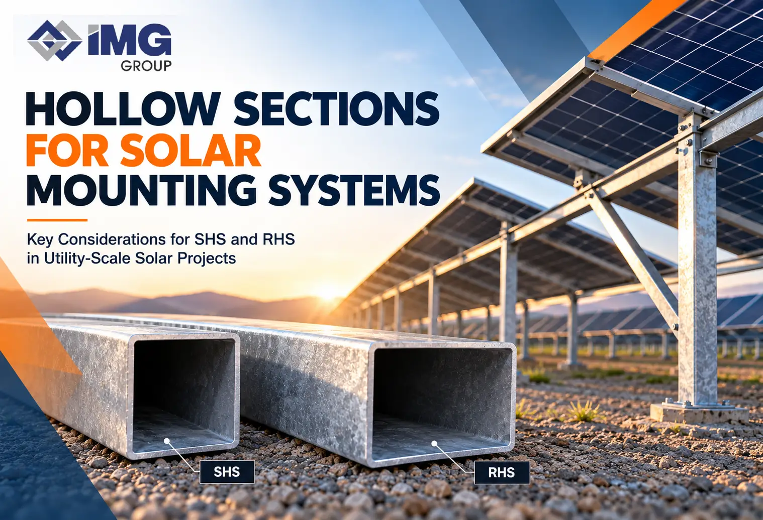
Solar mounting solutions might bring unique needs to the supporting steel parts, while appearing to be simple. Ground mounted systems must sustain thousands of solar modules and withstand wind, snow and other environmental pressures over its service life. At a utility scale, modest variations in weight, shape or durability of individual steel elements can have a significant influence.
So choosing steel for solar buildings is not a matter of finding the lightest available profile. The aim is to find the optimal balance between structural performance, material efficiency, corrosion resistance, fabrication and installation.
Many solar installation applications need the equilibrium that steel hollow parts often give. The closed cross-section geometry of these members makes them suitable for a wide range of structural applications and they can give useful resistance to bending, compression and torsional impacts while preserving relatively simple and consistent geometry for manufacture.
However, hollow portions are not the answer to all solar mounting systems. Other elements of the structure may be more appropriate for C, U and Z sections and for cold‑formed profiles particular to the project. Material selection is much more critical in utility scale solar installations because the same component can be duplicated thousands of times. A change in wall thickness or unit weight, even a little one, can mean several tonnes of steel on an entire solar farm. Too aggressive a reduction of weight at the same time might lead to problems with buckling, deflection, connections or long term durability.
This article discusses the application of hollow sections for solar mounting systems, comparing SHS and RHS, and the important criteria affecting their choice including structural loads, steel grade, wall thickness, corrosion protection, fabrication and material efficiency.
What Are Hollow Sections?
Hollow sections are structural steel sections with a closed cross-sectional shape, unlike open sections such as I, C or U profiles. Their geometry can be particularly useful in structures subjected to loads from different directions.
Solar mounting structures are primarily interested in the Square Hollow Sections (SHS) and Rectangular Hollow Sections (RHS):
Square Hollow Sections (SHS)
Square hollow sections have the same external dimensions in both major directions. A usual designation could be:
SHS 100 x 100 x 4 mm
This is a section with outside width and height of 100 mm and a nominal wall thickness of 4 mm.
Because of their symmetrical geometry, SHS have similar geometrical qualities along both major axes. This makes them suitable for use in posts, frames, supports and other members where loads may be applied in more than one direction.
This property can be important in case of solar mounting systems where structural members should be able to react to changing wind pressure and suction as well as forces transmitted via the supporting frame.
Rectangular Hollow Sections (RHS)
Rectangular Hollow Sections have different external dimensions for their width and height. A typical example could be:
RHS 120 × 80 × 4 mm
Unlike SHS, an RHS has different section properties about its two principal axes. This allows engineers to orient the section according to the dominant loading direction.
For example, where bending demand is considerably greater in one direction, an appropriately oriented RHS may provide a more efficient distribution of material than a square section of comparable weight. This makes RHS useful for beams, supporting frames and other members where the direction of structural loading is clearly defined.
What About Circular Hollow Sections?
Structural hollow sections also include Circular Hollow Sections (CHS). Their circular design gives uniform characteristics in all directions and can be beneficial for some structural applications.
However, SHS and RHS are typically particularly practical where flat surfaces make it easier to connect to brackets, plates and other mounting components. Therefore, this article focuses mostly on SHS and RHS for solar mounting systems, instead of discussing every form of hollow section in equal detail.
Hollow Section Is a Geometry, Not a Steel Grade
The grade of material should be distinguished from the section identification.
The section form and dimensions are shown by the marking SHS or RHS. It does not in itself show the strength of the steel.
For example you might say:
SHS 100 × 100 × 4 – S355
merges two separate pieces of information. The first part describes the section geometry and the notional wall thickness. S355 refers to the structural steel grade.
Both must be taken into account in the design. The section characteristics and weight are changed by altering the wall thickness and the required material strength is changed by changing the steel grade. Neither should be assessed in isolation from structural needs.
This differentiation becomes especially critical for large solar projects, where the optimum mix of section geometry, wall thickness and steel quality can greatly affect structural performance and total steel consumption.
Where Are Hollow Sections Used in Solar Mounting Structures?
The role of hollow sections for solar mounting systems is determined by the structural design of the installation. There is no uniform profile layout applied to all solar projects. The requirements of fixed-tilt systems, tracking systems and auxiliary structures may be extremely varied and hollow sections may be used exclusively for chosen portions of the supporting structure.
Where SHS and RHS are specified they are generally considered for members requiring a mix of bending resistance, compression capacity, stability and practical connecting surfaces .
Posts and Vertical Supports
Posts transfer loads from the solar mounting structure into the foundation or ground support system. Depending on the design, these members may be subjected to axial compression together with bending caused by wind and the geometry of the supporting frame.
SHS can be particularly useful for posts because their square geometry provides similar section properties about both principal axes. This can be advantageous where loading is not limited to a single direction.
RHS may also be used where the structural demands are more pronounced about one axis and the section can be oriented accordingly.
However, the choice of a hollow section for a post must also consider foundation design, connection details and installation method. Driven piles and other specialised solar foundations, for example, may use entirely different profile geometries.
Supporting Frames and Beams
Hollow sections can also form part of the frames that transfer loads from the module-supporting structure to the primary supports.
Here, RHS can offer useful design flexibility because its rectangular geometry allows the deeper dimension to be positioned in the direction where greater bending resistance or stiffness is required.
This does not automatically make RHS more efficient than an open section. The comparison must consider the complete structural system, including span, loading, connections, wall thickness and total section weight.
Bracing Members
Solar mounting structures must remain stable under changing environmental loads, particularly wind. Bracing members can therefore play an important role in transferring forces and maintaining the geometry of the supporting structure.
SHS and smaller RHS sections may be used as bracing members where their structural properties and connection details suit the design.
Their closed geometry can provide useful behaviour where loads are not confined to a single plane, although the final section should always be selected according to calculated forces rather than shape alone.
Equipment and Auxiliary Structures
A utility-scale solar project includes more than the structures directly beneath the PV modules. Steel may also be required for equipment supports, inverter structures, cable-support systems, access structures and other auxiliary frames.
Hollow sections can be suitable for many of these applications because SHS and RHS are available in a wide range of dimensions and wall thicknesses and can be incorporated into fabricated frames relatively easily.
This also allows a project to use hollow sections beyond the repetitive module mounting structure where appropriate.
Not Every Solar Structure Requires Hollow Sections
It is important not to treat SHS and RHS as the default solution for every component.
Solar mounting systems frequently use C, U, Z and other cold-formed sections, including profiles developed specifically for a particular mounting system. These open sections can provide excellent material efficiency, especially in highly repetitive structures where geometry has been optimised for a specific load path and connection method.
The decision should therefore be based on the role of the member rather than a preference for one profile family.
Hollow sections become particularly interesting when their closed cross-sectional geometry provides a useful combination of structural performance, stability and connection possibilities. Understanding why requires a closer look at how SHS and RHS behave under the loads encountered in solar structures.
Why SHS and RHS Work Well in Solar Structures
The suitability of SHS and RHS for solar mounting systems is closely related to their closed cross-sectional geometry. Unlike open profiles, hollow sections distribute material around the perimeter of the section, which can provide useful structural characteristics when members are subjected to bending, compression and torsional effects.
This does not mean that hollow sections are inherently superior to open sections. Their advantage depends on how the member is loaded and how effectively its geometry is used within the overall mounting system.
Structural Performance in More Than One Direction
One of the main characteristics of Square Hollow Sections (SHS) is their symmetrical geometry. Because the dimensions are equal about both principal axes, an SHS has similar geometric properties in either direction.
This can be useful for solar structures exposed to changing wind conditions. PV arrays present a relatively large surface area to the wind, and the resulting forces can generate pressure, uplift, suction and bending effects within the supporting structure.
Where a member needs to resist forces acting in more than one direction, SHS can therefore offer a practical structural geometry.
Rectangular Hollow Sections (RHS) behave differently. Their unequal dimensions produce different section properties about the major and minor axes. Engineers can use this intentionally by orienting the deeper dimension in the direction where greater bending stiffness or resistance is required.
For members with a clearly dominant loading direction, this can make RHS an efficient option.
Closed Sections and Torsional Behaviour
Another characteristic of hollow sections is their response to torsion.
Because SHS and RHS form closed sections, they generally provide greater torsional stiffness than comparable open sections where geometry and material distribution are otherwise suitable for comparison.
This can be relevant in solar mounting structures because loads are not always applied directly through the centre of a member. Module arrangement, brackets, connection points and wind loading can introduce eccentric forces that create torsional effects.
A hollow section may therefore be useful where the structural member is expected to resist a combination of bending and torsion.
The actual benefit must still be verified through structural analysis. Section dimensions, wall thickness, member length and connection conditions all influence performance.
Performance as Compression Members
Hollow sections are also widely used as compression members in general steel construction.
Their geometry can provide an efficient distribution of material around the section’s centroid, which can be advantageous for posts and other members subjected to axial compression.
For SHS in particular, similar properties about both principal axes can be useful where buckling needs to be considered in more than one direction.
However, higher material strength or a closed section does not eliminate buckling risk. A solar mounting post can still be governed by member slenderness, effective length, local buckling or overall stability rather than the yield strength of the steel itself.
Wall thickness therefore becomes an important part of hollow section selection.
Practical Surfaces for Connections
SHS and RHS also provide flat external faces, which can simplify certain types of connection.
Brackets, plates and other fabricated components can be positioned against these surfaces without the curved connection interface associated with circular hollow sections. This can be useful in repetitive solar structures where connection geometry must remain consistent across large quantities of components.
At utility scale, this repeatability matters. A mounting system may contain thousands of similar connections, so fabrication complexity and installation time can have a significant effect on the overall project.
At the same time, hollow section connections require careful design. Access to the inside of the section can be limited, and welding, bolting, drainage and galvanizing requirements may affect how the connection is detailed.
For this reason, the structural advantages of SHS and RHS should always be considered together with fabrication and connection requirements.
Ultimately, the geometry of a hollow section only becomes useful when it responds effectively to the forces acting on the structure. In solar mounting systems, those forces are strongly influenced by environmental conditions—particularly wind and snow loads.
Structural Loads in Solar Mounting Systems
Solar mounting structures are relatively lightweight, but the forces acting on them can be substantial. Large photovoltaic arrays create extensive exposed surfaces, and their inclination means that environmental loads can generate forces in several directions at the same time.
For this reason, selecting an SHS or RHS for a solar mounting system requires more than checking the weight per metre or nominal wall thickness. The section must be evaluated according to the loads transferred through the complete mounting structure.
Wind Loads
Wind is generally one of the most essential design factors for ground-mounted solar arrays.
Large aerodynamic surfaces are possible with PV modules. Depending on wind direction, module tilt, array design and the location in the solar field, the structure may be exposed to positive pressure, suction and uplift.
The forces are transmitted from the modules via the rails or supporting members to the main frame, posts and finally to the foundations.
The wind effects could have different impacts over a solar farm. The rows closer to the edge of an array can face different conditions than further inside the field. The terrain, elevation and local wind conditions might also influence the design loads.
Therefore, the dimensions of hollow sections should not be decided only on the basis of module weight. All bending, axial forces, torsion and overall stability may have to be considered.
Snow Loads
In areas of appreciable snowfall, snow can impose a substantial additional vertical stress.
The effect depends on variables such as local climate, module tilt, array geometry and snow accumulation. Uneven accumulation may also provide loading circumstances different from a simple evenly distributed load.
This might raise bending and deflection demands for beams and supporting structures. The transfer of these loads through the structure can also cause posts to be subjected to increased compression forces.
In some designs it may be helpful to have an RHS with its deeper dimension orientated in the primary bending direction, whereas SHS may be suitable if more balanced qualities about both principal axs are desired.
The right option still relies on structural calculations rather than on section shape only.
Dead Loads
Dead load includes the permanent weight of the PV modules and the mounting structure itself, including rails, brackets, fasteners and steel members.
Compared with some conventional steel structures, these loads may appear modest. At utility scale, however, material efficiency remains important because the same structural components are repeated across thousands of modules.
Reducing unnecessary steel weight can therefore have a significant effect on total project tonnage.
The objective should not be to minimise wall thickness without limitation. Excessive reduction can increase susceptibility to local buckling, deformation and connection-related problems.
Installation and Maintenance Loads
The construction should also perform during installation and over the operational life.
During the installation of modules and structural components, temporary loading situations can arise. Maintenance activities can provide additional loads or load combinations which are distinct from normal operating conditions.
These situations should be incorporated in the appropriate structural design criteria rather than presuming that the full array represents the only relevant loading scenario.
Load Combinations Matter
Wind, snow, dead load and other actions are not evaluated independently in structural design. Applicable design standards define how different actions and load combinations should be considered for ultimate and serviceability limit states.
This is particularly important when selecting hollow sections.
A section may provide sufficient resistance against yielding but still be unsuitable because of deflection, local buckling, global buckling or stability requirements. Similarly, increasing the steel grade may improve strength without solving a problem caused primarily by section geometry or stiffness.
The appropriate hollow section is therefore the result of considering loads, geometry, wall thickness and steel grade together.
Once the design loads are established, one of the next decisions is whether a Square Hollow Section or Rectangular Hollow Section provides the more suitable geometry for the member.
SHS vs RHS for Solar Mounting Systems
Square Hollow Section (SHS) and Rectangular Hollow Section (RHS) can be utilised as solar mounting structures but their differing geometries make them ideal for different structural circumstances. The choice should be made on the basis of load direction, member function, span, connection design and the desired compromise between strength, stiffness and weight.
| Feature | SHS | RHS |
|---|---|---|
| Cross-section | Square | Rectangular |
| Principal-axis geometry | Similar in both directions | Different about each axis |
| Bending behaviour | Balanced between principal axes | Can be oriented toward the dominant bending direction |
| Typical solar applications | Posts, frames, bracing | Beams, frames, supporting members |
| Connection surfaces | Flat on four sides | Flat on four sides |
| Best suited to | Multidirectional or balanced structural demands | Direction-specific structural demands |
When Can SHS Be a Better Choice?
An SHS is characterised mostly by symmetry. It has the same geometric features concerning its two primary axs because of its equal external width and height.
This may be useful for solar mounting posts and frame parts that may see considerable stresses in more than one direction . For example, the wind on a PV array can transmit longitudinal and transverse forces through the supporting structure.
SHS can also ease cases where the orientation of the section should not significantly modify its principal-axis attributes.
That does not mean SHS is the most efficient solution by default. If one loading direction is dominant, the greatest utilisation of available steel may not always be achieved by dispersing the material evenly about both axes.
When Can RHS Be More Efficient?
RHS has varied depth and width, thus it offers other possibility.
Let’s consider an RHS of 120 x 60 mm. If the 120 mm dimension is in the direction of the principal bending, the section can give more stiffness and resistance to bending about that axis than if it were rotated 90°.
Engineers can use this differential to better align the section shape with the projected load path.
This means that RHS is particularly relevant for members such as supporting beams and frames where the loading is mostly directed.
In a large solar installation this kind of optimisation might also affect steel use. The desired performance can be achieved by selecting a more appropriate section geometry to the structural need, without adding material when the advantage is minimal.
SHS or RHS: Which Is Better for Solar Structures?
There is no universal winner.
An SHS may be appropriate for a post exposed to structural demands in both principal directions, while an RHS may be more efficient for a beam where bending is concentrated about one axis. Another solar mounting system may use neither because a cold-formed C or Z section provides a better solution.
Even within the SHS and RHS families, the designation alone is not enough.
For instance:
SHS 100 x 100 x 3 mm
or
SHS 100 x 100 x 5 mm
have the same exterior dimensions but very varied cross sectional characteristics and unit weights.
The same is true for the grade of the steel. In terms of material strength, an RHS produced from S355 does not behave the same as a comparable section produced from S235.
The practical choice therefore is more than simply a choice between square and rectangle geometry. The section dimensions, wall thickness and steel grade are taken together to check whether the member satisfies the strength, stiffness, stability and connection requirements.
Thus, steel grade and wall thickness are the next crucial aspects to consider when choosing hollow sections for solar mounting systems.
Steel Grade and Wall Thickness
Selecting the correct hollow section for a solar mounting structure requires more than choosing between SHS and RHS. Two of the most important variables are steel grade and wall thickness, because both influence structural capacity while wall thickness also has a direct effect on section properties and weight.
A typical specification may therefore look like:
SHS 100 × 100 × 4 mm – S355
Here, 100 × 100 mm defines the external dimensions, 4 mm is the nominal wall thickness, and S355 identifies the structural steel grade.
How Steel Grade Affects the Section
Common structural steel grades include S235, S275 and S355. As discussed in our guide to structural steel grades, the numbers relate to specified minimum yield strength for defined thickness ranges and product standards.
Moving from S235 to S355 provides higher yield strength, but this does not mean that every S355 hollow section can automatically be made thinner than an equivalent S235 section.
Higher-strength steel is most beneficial where material strength is a governing design criterion. If the member is controlled by deflection, buckling, local instability or connection behaviour, increasing the steel grade alone may provide limited benefit.
This distinction is particularly important for solar structures because many members are relatively slender.
Why Wall Thickness Matters
The wall thickness influences a lot more than just the amount of steel in the section.
Increasing the wall thickness modifies the cross section area and section characteristics which may influence the resistance to axial stresses, bending and local buckling. Also raises the unit weight of the profile.
If the wall thickness is decreased, the amount of steel used can be reduced, but additional design limits may be introduced.
For example, take two pieces of the same external dimensions:
SHS 100x100x3 mm.
SHS 100 x 100 x 5mm
They are diverse in structure, although they are in the same outward envelope. They do not have the same cross sectional area, mass per metre and structural qualities.
This is extremely relevant for utility-scale solar installations as even a minor reduction in kg/m can be amplified over several kilometres of steel sections.
Higher Strength Does Not Automatically Mean Lower Weight
It can be tempting to replace a lower-grade steel with S355 and simply reduce the wall thickness. In practice, structural optimisation is more complex.
The elastic modulus of conventional structural steels such as S235 and S355 is essentially comparable. Therefore, moving to a higher steel grade does not produce a proportional increase in elastic stiffness.
If deflection governs the design, higher yield strength alone may therefore not allow the section dimensions to be reduced significantly.
Buckling presents a similar issue. The performance of a slender member depends not only on material strength but also on factors such as section geometry, member length, boundary conditions and slenderness.
Local buckling of thin walls can also become increasingly important as wall thickness is reduced.
Finding the Right Combination
The objective is therefore not to specify the highest steel grade or the thinnest possible wall.
The goal is to identify the combination of:
section geometry + dimensions + wall thickness + steel grade
that satisfies the structural requirements while using material efficiently.
For large solar projects, this optimisation can have a substantial economic effect. Saving a relatively small amount of steel from each repetitive member can reduce total project tonnage considerably. But those savings only make sense when the resulting section continues to satisfy strength, serviceability, stability, fabrication and connection requirements.
Structural efficiency is also only part of the equation. Solar mounting structures remain outdoors for decades, which means the selected hollow sections must also be protected against one of steel’s most important long-term challenges: corrosion.
Corrosion Protection for Solar Steel Structures
Solar mounting structures are expected to remain outdoors for many years, often with limited opportunities for major maintenance. During that time, the steel can be exposed to rain, humidity, temperature changes, condensation, airborne salts and other environmental conditions that promote corrosion.
For this reason, corrosion protection is a fundamental part of hollow section selection for solar mounting systems, rather than a treatment that should be considered only after the structural design has been completed.
Why Corrosion Protection Matters in Solar Projects
Corrosion is not simply a visual issue. Over time, material loss can reduce the effective thickness of a steel component and affect its structural performance.
This is especially relevant when relatively thin-walled sections are used to optimise the weight of a solar mounting system. A small amount of material loss represents a greater proportion of the total wall thickness when the original section is already thin.
The required protection therefore needs to reflect the expected service life and environmental conditions of the project.
A solar farm in a relatively dry inland environment does not necessarily require the same corrosion protection strategy as a project located near the coast, in an industrial atmosphere or in an area with persistent high humidity.
Galvanized Hollow Sections
Zinc coatings are commonly used to preserve steel components against corrosion. The zinc coating functions as a barrier to the environment from the steel substrate and can provide a sacrificial protection when little damage exposes the underlying steel.
But the phrase “galvanized steel” can apply to different production and coating processes.
Another choice is steel made from continually zinc-coated material before the final component is built. Depending on the manufacturing procedure this strategy may be applicable for some hollow sections and cold formed solar mounting components.
Another method is hot dip galvanising after manufacture, which is the dipping of the fabricated steel component in molten zinc. This allows the application of a zinc coating on fabricated surfaces after the cutting, drilling and welding operations have been finished.
The two approaches are not equivalent.
Fabrication Can Affect Corrosion Protection
The order of the production procedures is of special significance.
Cutting, drilling or welding of a previously coated steel component can locally disturb or destroy the original protective layer. Depending upon the coating system, fabrication method and project requirements these locations may require proper treatment.
Where components are hot dip galvanised after manufacture the design itself must be compatible for the galvanising process.
This means that for hollow parts elements such as venting and drainage holes will need careful thought. Hollow areas must allow process fluids, gases and molten zinc to pass safely through the component during treatment.
These needs should consequently be incorporated into the component design, not considered simply after production.
Coating Selection Should Reflect the Environment
There is no one zinc coating specification that is best for all solar projects.
The choice of system is dependent on variables such as atmospheric exposure, estimated service life, component geometry, production route and maintenance plan.
Coating thickness should not be regarded without context. The length of the protection is determined by the interaction between the coating system and the corrosiveness of the environment where the structure will operate.
This therefore becomes a lifetime concern for utility-scale projects. Selecting a corrosion protection system based solely on the lowest upfront cost can result in increased maintenance or replacement costs at a later stage of the project.
The aim, therefore, is to combine structural efficiency with adequate long-term durability.
Corrosion protection of SHS and RHS used in solar mounting systems should preferably be considered combined with wall thickness, steel grade and fabrication method from the beginning of the design process.
This leads immediately to a further mandatory feature of the selection of hollow pieces: how the sections are manufactured and joined to the remainder of the solar mounting structure.
Fabrication and Connection Design
Structural performance alone does not determine whether a hollow section is suitable for a solar mounting system. The section must also be practical to cut, drill, weld, coat, transport and connect.
This becomes particularly important in utility-scale solar projects, where the same component or connection may be produced thousands of times. A detail that adds only a small amount of fabrication time to one member can have a significant effect when repeated across an entire project.
Bolted Connections
Bolted joints are extensively employed in solar mounting structures because they can facilitate on-site assembly and diminish the volume of field welding.
SHS and RHS have flat faces which are useful for brackets, plates and other connecting components. Connections are provided by means of external brackets, through-bolts, welded plates or other fastening mechanisms, according to the design.
A major limitation of using hollow sections, however, is that access to the interior of the section may be limited.
A standard bolt and nut setup may not always be viable if the installer cannot reach the internal face of the piece. Therefore, connection design should be considered early, especially when closed sections are used for posts or frame members.
Welded Connections
Welding provides another method of connecting hollow sections to base plates, brackets, gusset plates and other structural components.
Fabrication in a controlled workshop environment can allow complex assemblies to be produced before they reach the project site. This may reduce the number of operations required during installation.
At the same time, welding introduces several considerations.
Heat from welding affects the local material and any existing protective coating. If the steel has already been galvanized or otherwise coated, the connection and subsequent corrosion protection procedure must be properly specified.
For structures intended to be hot-dip galvanized after fabrication, welding, drainage, venting and component geometry should all be coordinated with the galvanizing process.
Base Plates, Brackets and Connection Plates
Hollow sections used as posts or structural frames are rarely isolated components. They normally interact with other fabricated steel parts.
A typical connection may include a hollow section together with a:
- base plate,
- bracket,
- gusset or connection plate,
- module-support component,
- foundation connection.
The behaviour of the connection can influence the design of the hollow section itself.
For example, very thin walls may create local deformation or connection-capacity limitations even when the overall member has sufficient global resistance. Increasing steel grade alone does not necessarily solve these local connection issues.
This is another reason why wall thickness should not be reduced solely on the basis of yield strength.
Fabrication Accuracy at Utility Scale
Dimensional consistency becomes increasingly important as the size of a solar project grows.
Hole positions, member lengths, section dimensions and connection geometry must remain within the required tolerances so that components manufactured in large quantities can be assembled efficiently on site.
Small inconsistencies can lead to alignment problems, additional drilling, installation delays or difficulty fitting prefabricated components together.
For highly repetitive structures, manufacturing repeatability can be almost as important as material efficiency.
A slightly lighter section offers little practical advantage if its connection design makes fabrication or installation significantly more complicated.
Design for Efficient Production and Installation
The most effective hollow section solution therefore considers the complete production chain:
material → section → cutting → drilling → welding → corrosion protection → transport → installation
Optimising only one stage can shift costs or problems to another.
For example, reducing wall thickness may save steel but complicate connections. Adding numerous welded brackets may simplify site installation but increase factory fabrication time. Selecting a larger section may increase material weight but potentially simplify the overall frame or reduce the number of components.
In utility-scale solar projects, these trade-offs become especially important because relatively small changes are multiplied across thousands of structural members.
This is why hollow section optimisation should ultimately be evaluated not only in terms of individual member performance, but also in terms of total steel weight and project-wide material efficiency.
Weight Optimisation in Utility-Scale Solar Projects
In a small steel structure, reducing the weight of an individual member by a few kilograms may have a limited impact on the overall project. In a utility-scale solar installation, the same structural member can be repeated thousands or even tens of thousands of times.
This repetition makes weight optimisation one of the most important considerations when selecting hollow sections for solar mounting systems.
A relatively small improvement in unit weight can translate into a significant reduction in total steel tonnage.
Small Weight Differences Become Significant at Scale
Consider a simplified example.
If an alternative hollow section reduces the steel weight by just 1 kg per structural member, and the project contains 50,000 identical members, the total material difference becomes:
1 kg × 50,000 = 50 tonnes of steel
The impact can become even larger when optimisation is applied across several types of posts, beams, frames and bracing members.
This is why engineers and procurement teams working on large solar projects often evaluate sections in terms of kg/m, not simply their external dimensions.
However, reducing steel weight should never become the sole design objective.
The Lightest Section Is Not Necessarily the Most Efficient
A lighter section will minimise material usage, but must still meet all essential structural criteria.
If the wall thickness is reduced too much there is a risk of local buckling or the connections deforming. If you choose a smaller area you may get more deflection. Higher strength steel may increase the resistance to yield but may provide little benefit where the design is governed by stiffness or buckling.
So the goal isn’t simply:
minimum steel weight but: minimum practicable steel weight which securely satisfies all design requirements.
This is a crucial differential in solar mounting structures, in which relatively slender elements and repetitive connections can make stability and serviceability equally as vital as material strength.
Optimising Geometry Before Adding Steel
Section geometry can sometimes provide greater efficiency than simply increasing wall thickness.
For example, where a member is primarily subjected to bending about one axis, an appropriately oriented RHS may provide a more useful distribution of material than increasing the thickness of a smaller section.
Similarly, changing the external dimensions of an SHS or RHS can alter section properties considerably without requiring a proportional increase in steel weight.
This allows engineers to evaluate several variables together:
external dimensions → wall thickness → section orientation → steel grade → member length
The most efficient combination depends on the structural role of the member.
Weight Reduction Affects More Than Material Cost
Lower steel tonnage can also influence other parts of a utility-scale solar project.
Reducing the weight of thousands of structural components can affect transportation requirements, handling, lifting, storage and installation. Lighter individual components may also be easier to manage during repetitive site assembly.
However, these benefits must be considered alongside fabrication and procurement.
A theoretically optimised section that requires unusual dimensions, difficult fabrication or limited production quantities may not provide the lowest overall project cost.
Availability therefore matters.
For large projects, a slightly heavier section that can be manufactured consistently and supplied in the required quantities may sometimes be commercially more practical than a theoretically lighter alternative with limited availability.
Optimisation Should Consider Total Project Value
The best hollow section should therefore not be selected solely according to price per tonne or weight per metre.
A more complete evaluation considers structural performance, total tonnage, fabrication requirements, corrosion protection, transport, installation and supply availability.
At utility scale, this project-wide approach can produce meaningful savings without compromising structural reliability.
Achieving that balance also depends on consistent material quality. When thousands of sections are supplied for the same project, dimensions, wall thickness, steel grade and documentation need to remain controlled from one production batch to another.
This makes standards, material quality and traceability the next important part of hollow section selection.
Standards and Material Quality
For utility size solar projects, specifying the precise section geometry is only part of the story. The provided hollow portions must also meet the appropriate dimensions, mechanical and documentation standards.
This is particularly critical when substantial volumes of SHS and RHS are employed on the same project. Small variances in dimensions, wall thickness or material qualities can cause problems in manufacture, assembly and structural performance.
EN 10219 and EN 10210
Two important European standards for structural hollow sections are:
- EN 10219 – Cold formed welded structural hollow sections
- EN 10210 – Hot finished structural hollow sections
These standards set specifications for dimensions, tolerances, material qualities and technical delivery circumstances for structural hollow sections.
This is a significant difference between cold formed and hot finished items, in that the manufacturing path impacts the product specification and applicable standard. Project documentation should therefore specify the hollow section type required, rather than a generic “steel tube” description.
Dimensional Accuracy
Dimensional uniformity is important in solar mounting systems as structural sections are often joined using prefabricated brackets, plates and drilled holes.
Important parameters are:
exterior measurements, wall thickness, straightness, length of section and shape of corner.
If these are different outside of permitted tolerances, connection alignment can be troublesome during fabrication or site installation.
The dimensional control has a direct effect on the installation efficiency of highly repetitive solar mounting systems. ### Steel Grade Verification
Steel Grade Verification
If a project requires S355 then the delivery of a piece with the right external dimensions but a lower quality material grade is not in accordance with the specification.
Similarly, steel grade and section geometry should not be viewed as interchangeable characteristics.
A larger section in S235 does not automatically mean a smaller section in S355, unless structural calculations show that the alternative meets all applicable standards.
Material identity should thus be traceable during the manufacture and distribution.
EN 10204 3.1 Inspection Documentation
EN 10204 Type 3.1 inspection certificates are frequently utilised for several structural steel projects for the purpose of material traceability and verification of stated test findings.
A 3.1 certificate can contain, for example:
steel grade, chemical composition, mechanical characteristics, heat number and test results.
This allows you to trace the provided material to the correct production batch.
This data can be especially significant for international solar projects, because steel may go through numerous phases of manufacture, coating, shipment and installation before to its final structural location.
Coating Quality Also Needs Control
When galvanised hollow parts are provided, the quality control should not only be limited to the base steel.
The coating system shall comply with the project specification and the continuity, thickness and application method shall be controlled in accordance with the relevant criteria.
This is particularly critical following fabrication procedures like cutting, drilling or welding, where corrosion protection may be locally damaged.
Consistency is as important as nominal specification in large solar installations.
When a batch fulfils the necessary geometry, grade and coating quality, following deliveries shall also match the same criteria.
Traceability Across Large Projects
Utility-scale solar farms might demand thousands of tonnes of steel that are delivered in a number of production and delivery phases.
Keeping track of traceability allows project teams to validate that the delivered portions meet the authorised specification throughout the project.
This covers not just the steel grade but also
section dimensions, wall thickness, production standard, coating system and inspection documentation.
Good management of materials decreases the chances of variation between batches and helps both the quality of fabrication and long term performance of the structure.
Once these technical and quality requirements are identified, the last step is to bring them together into a practical selection process for choosing the proper hollow pieces for a solar mounting project.
How to Select Hollow Sections for a Solar Mounting Project
There are various design and project factors that need to be addressed together to be able to select the proper hollow section for a solar mounting system. Rarely is the optimal option decided by a single characteristic such as steel quality, wall thickness or unit weight.
A sensible selection procedure should start with the structural demands of the system and then go on to geometry, material, durability, fabrication and supply factors.
Start with the Structural Loads
The first thing is to understand the forces acting on the member.
This can include:
- wind actions,
- snow loads;
- dead load;
- installation and maintenance loads
- axial loads,
- The moment of bending,
- twisting effects.
The importance of each load is determined by the function of the member. For example, a vertical post has different structural requirements than a horizontal support beam or bracing element.
This loading evaluation establishes the basic performance needs of the section.
Select the Appropriate Section Geometry
After knowing the loading direction, the designer can determine which SHS or RHS is the most appropriate geometry.
SHS can be useful if both the principal axs are required to have identical features.
RHS provides greater flexibility where bending is predominantly in one direction, because the deeper dimension can be orientated along the main loading direction.
At this stage the member length, the support conditions as well as the external dimensions should be examined simultaneously.
Determine Wall Thickness
The thickness of the wall plays a role in both steel consumption and structural performance.
Increasing wall thickness may improve resistance to axial stresses, bending and local buckling but increases the weight per metre.
The tonnage of steel can be reduced by reducing the wall thickness, but this can also lead to limits as regards:
local buckling, connection design, weldability and durability.
The specified thickness should therefore fulfil the full structural design and not merely weight minimisation.
Choose the Steel Grade
The next consideration is the grade of material.
Grades like S235, S275 and S355 offer different levels of specified yield strength.
Where material resistance is controlling the design, higher strength steel can bring benefits, but it should not be assumed automatically that S355 will give a lighter construction than S235.
If a part is dominated by stiffness, buckling or connection behaviour, a change in steel grade alone might have little effect.
Thus, the steel grade has to be considered in association with the geometry of the section and the wall thickness.
Define the Corrosion Protection System
Solar mounting structures are exposed to outside environments over their whole service life.
The corrosion protection system should reflect: project site, weather conditions, intended service life, manner of manufacture and maintenance strategy.
Depending on the project this could be continuously galvanised material, hot dip galvanising after manufacture or another required coating technique.
The coating strategy should be chosen early as it can affect fabrication details, venting, drainage and connection design.
Review Connections and Fabrication
However, connection details of a structurally efficient hollow part may be difficult to fabricate or assemble and can make the section unsuitable.
Therefore the connection design should be checked before the section specification is finalised.
Key questions include whether the member will be drilled, welded or bolted, whether access to the inside of the hollow part is necessary and whether the component will be galvanised before or after manufacture.
Repeatability is especially critical for large projects Consider Availability and Total Project Cost
Consider Availability and Total Project Cost
Theoretically the lightest portion is not necessarily the most realistic commercial option.
Highly specialised sizes may be available for a minor weight saving but with longer lead times, increased fabrication costs or limited availability.
So, the final decision should consider:
structural performance, total steel tonnage, fabrication, coating, transport, installation and supply reliability.
This is a more realistic indicator of project efficiency than just looking at price per tonne.
For utility size solar projects the most appropriate hollow part is typically the one that delivers the requisite structural performance with the minimum practical impact on the whole project – not the smallest or lightest section that can be sourced.
Conclusion – Hollow Sections for Reliable Solar Structures
Hollow sections can play an important role in the structural design of solar mounting systems, particularly where a project requires a combination of strength, stiffness, stability and practical fabrication.
Both Square Hollow Sections (SHS) and Rectangular Hollow Sections (RHS) can be suitable for posts, frames, beams, bracing members and auxiliary structures. Their closed geometry can provide useful resistance to bending, compression and torsional effects, while their flat external surfaces can simplify many types of structural connection.
However, hollow sections should not be selected simply because they are strong or easy to fabricate.
A reliable solar mounting structure depends on the correct combination of:
section geometry, wall thickness, steel grade, corrosion protection, connection design, fabrication quality and material traceability.
The most appropriate solution may be an SHS in one part of the structure, an RHS in another, or a completely different profile family where open or project-specific cold-formed sections provide greater efficiency.
For utility-scale solar projects, material optimisation becomes especially important because the same structural component may be repeated thousands of times. Small differences in unit weight can translate into significant changes in total steel tonnage, transport requirements and installation costs.
At the same time, weight reduction should never compromise structural performance. A lighter section is only valuable when it continues to satisfy requirements related to strength, deflection, buckling, connections, durability and service life.
Corrosion protection is equally important. Solar structures are expected to remain outdoors for decades, so galvanizing or other specified protection systems should be considered as part of the original design rather than as an afterthought.
Standards such as EN 10219 and EN 10210, together with appropriate material documentation such as EN 10204 Type 3.1 inspection certificates, also help ensure that supplied hollow sections meet the dimensional, mechanical and traceability requirements of the project.
Ultimately, there is no single hollow section that is suitable for every solar mounting system. The best solution is the one that matches the structural demands of the project while providing an efficient balance between performance, durability, manufacturability and total project cost.
IMG Group supplies SHS and RHS hollow sections in different dimensions, wall thicknesses and structural steel grades for international solar and structural steel projects. Project-specific requirements can be supported with appropriate material documentation, quality control and supply planning for both standard and large-volume applications.