


Blog
Steel Profile Selection for Utility-Scale PV Projects in 2026

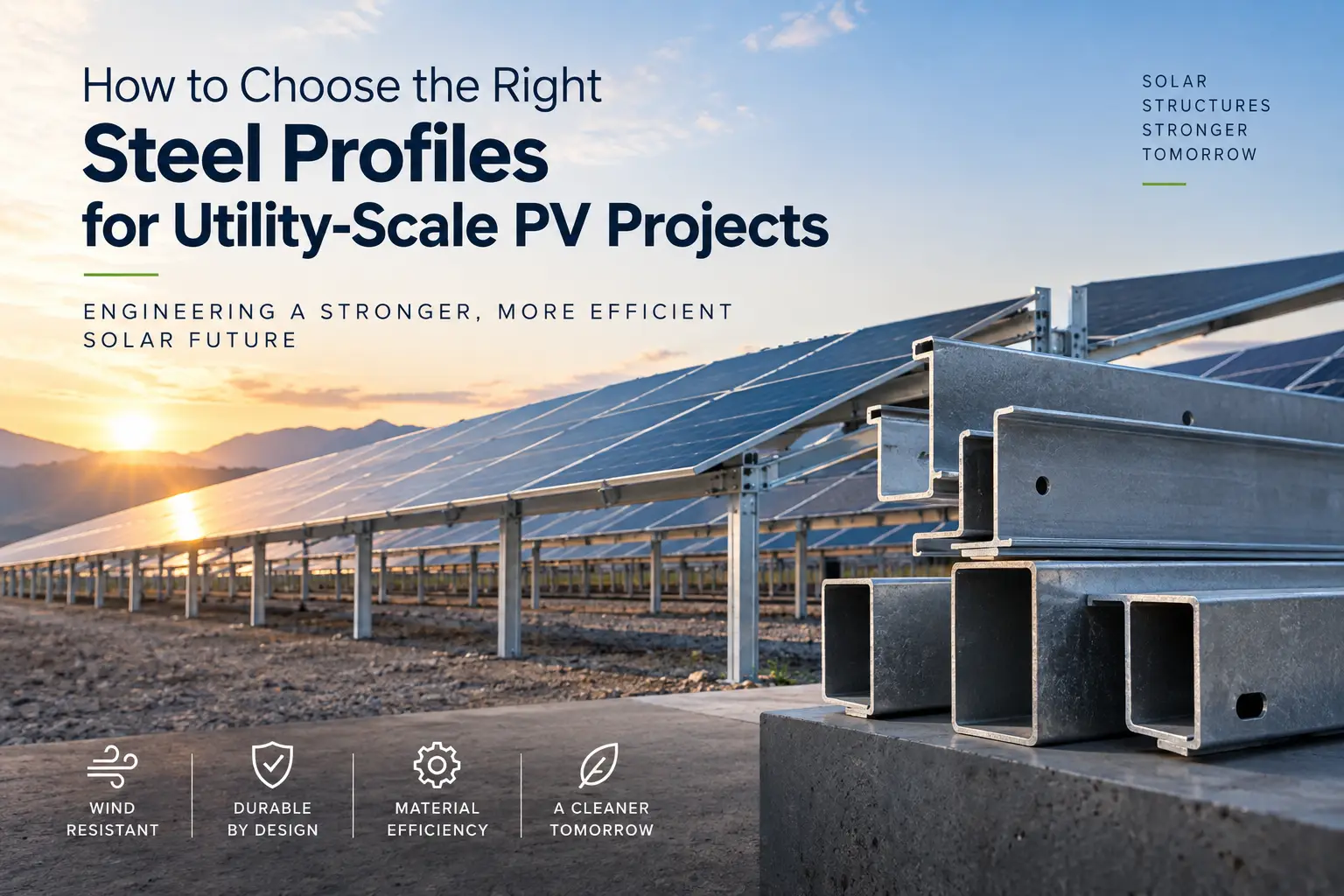
Utility scale photovoltaic projects impose very different demands on structural systems than small commercial or rooftop solar installations. A large ground-mounted PV plant could have thousands of modules supported by a complex framework of steel posts, beams, rails, bracing members, and auxiliary structures. At this level, the choice of the right steel profiles for solar projects is an important engineering and economic decision.
The main task of a solar mounting structure is simple: to secure photovoltaic modules in place for the operational life of the plant. However, to do so reliably requires the structure to be resistant to a combination of permanent and variable loads. The wind, the snow, the weight of the system itself, the conditions of the local terrain and the exposure to the environment all affect the structural design. In tracking systems there are moving components and varying panel orientations which also need to be considered and reflected in the supporting steel structure.
Therefore, the selection of steel profiles for utility-scale PV projects is not only about choosing a section that can carry a certain load. The efficiency of the completed structure is controlled by the profile geometry, wall thickness, steel grade, span, connection design, corrosion protection, fabrication requirements and erection conditions.
In larger projects the efficiency of materials is of particular importance. A difference of only a few kilograms in any one structural member might seem trivial. But multiplied thousands of times over with posts and other supporting elements, it can make a big difference in the total tonnage of steel. This difference can influence the material used, the transportation requirements, the handling, the installation process, and the overall costs of the project.
At the same time, the reduction of steel weight cannot be at the expense of structural reliability. The best solution is not always the lightest profile but the section which provides the required strength stiffness stability durability and manufacturability with an optimised quantity of material.
Long term exposure adds another dimension to the selection process. Utility-scale solar mounting structures are exposed to the elements for decades and can be installed in environments ranging from dry inland areas to coastal or industrial areas with significantly higher corrosion risks.
Therefore, selection of the correct steel product and corrosion protection system is an inherent part of the design for the expected service life of the PV plant.
In this guide we will explore the key factors for selecting steel profiles for utility-scale PV projects, including profile types, structural loads, steel grades, corrosion protection, material efficiency, applicable standards and quality documentation. The aim is to understand the interaction of these factors to develop solar mounting structures which are structurally reliable, economical and suitable for long term operation.
The Role of Steel in Utility-Scale PV Structures
Steel is the structural backbone to many utility-scale PV systems. Unlike the production and management of electricity by photovoltaic modules and electrical equipment, the supporting structure must maintain those components in a secure position under changing environmental conditions, over the life of the solar plant.
For ground-mounted projects, the steel structure serves as the interface between the photovoltaic modules and the foundation or ground anchorage system. Depending on the mounting concept, the steel members can be used as driven posts, columns, beams, purlins, bracing elements, module supports and components of auxiliary structures. Each member performs a different structural function and, therefore, it does not make sense to use the same profile geometry throughout an entire project.
Fixed-Tilt PV Structures
A fixed-tilt solar mounting system holds PV modules at a fixed angle and orientation. The supporting structure must maintain this geometry while it transfers loads from the modules, through the steel members, and into the foundations.
The choice of profile is dictated by the module configuration, row geometry, support spacing, terrain, wind pressure, snow accumulation and the structural design of the mounting system. Cold-formed profiles, channels, hollow sections or other structural steel sections can be incorporated in different parts of the system, based on these requirements.
In particular, optimisation is valuable for fixed-tilt projects since they can comprise a very large number of repetitive structural assemblies. Even small changes to section geometry or wall thickness can impact the total amount of steel needed for an entire solar farm.
Single-Axis Tracker Structures
Steel also plays an important role in single-axis tracker systems that rotate photovoltaic modules throughout the day to follow the sun’s path. Trackers have moving parts and therefore structural and mechanical considerations that do not apply to fixed structures.
Supporting steel has to take the loads generated at different module orientations without losing alignment and stability. The wind behaviour is of special importance as the aerodynamic forces acting on the module array may change with the change of the tracker position.
Structural members used in the vicinity of tracker systems, therefore, may have different stiffness, geometry, connection and dimensional requirements than those used in conventional fixed-tilt structures. The decision of profile should be coordinated with the design of the tracker not treated as a separate materials decision.
Structural Efficiency at Solar-Farm Scale
One of the defining features is the repetition of the utility scale PV construction. One structural solution may be repeated on the site hundreds or thousands of times. Hence, the optimisation of structural steel is very important.
An unnecessarily heavy profile multiplied through thousands of members can add a great deal to the total tonnage of steel. In contrast, if the section thickness or dimensions are reduced without considering the strength, stiffness, buckling, connections and environmental loads, the performance of the structure may be deteriorated.
So the idea is to put the steel where it will be most effective structurally. Depending on which member is predominantly resisting bending, compression, tension, torsion, or a combination of forces, different portions of the mounting system may require different section geometries.
The link between the structural function and the section geometry is the reason for the multitude of types of steel profiles in utility-scale solar projects. The second step, which is to understand the characteristics of those sections, is to know the characteristics of the steel profiles for PV mounting structures.
Which Steel Profiles Are Used in Solar PV Projects?
There is no single steel profile that can be considered the standard solution for every utility-scale PV project. The appropriate section depends on the structural function of the member, mounting system design, loading conditions, connection details, manufacturing method, and installation requirements.
A large ground-mounted solar structure may therefore incorporate several different section geometries. The objective is not to use the strongest or heaviest profile throughout the system, but to match each structural member with a section that provides the required performance with efficient material use.
C Profiles and Channels
C-sections and channel sections are widely used in lightweight structural systems because of the useful bending stiffness of the open geometry and the relative low weight. Depending on the design of the mounting system, they can be incorporated into posts, beams, purlins, module-supporting members, and secondary structural members of solar mounting structures.
Cold formed C sections are well suited to repetitive production. Sizes, thicknesses, hole patterns and connection details are adaptable to the particular mounting system requirements which can ease shop fabrication and field assembly.
However, open sections have to be carefully engineered in terms of torsional forces or buckling. The orientation, unsupported length, points of connection and direction of loading thus form part of the complete structural system.
U Channels
U channels may be used in support frames, secondary members, connection zones and other structural elements where an open section provides an efficient solution. Their flat surfaces also lend themselves to drilling, bolting, and attaching brackets or connection plates.
Similar to C sections, the structural suitability of a U channel is not only dependent on its dimensions or wall thickness. Load direction and connection configuration can greatly affect its behaviour, especially where eccentric loading introduces additional torsional effects.
For utility-scale PV projects this means that profile geometry and connection design are closely related decisions rather than separate ones.
Z Profiles
Z profiles provide another material-efficient option for lightweight steel structures. Their geometry can be particularly useful where members must overlap or form continuous structural lines across several supports.
In solar applications, Z sections may be considered for secondary framing and supporting elements where their geometry matches the structural concept of the mounting system. Their relatively efficient use of steel can be valuable in large projects where the same section is repeated thousands of times.
As with other cold-formed profiles, wall thickness, local buckling behavior, span, connection arrangement, and manufacturing tolerances must all be considered during design.
Square and Rectangular Hollow Sections
Square Hollow Sections (SHS) and Rectangular Hollow Sections (RHS) provide a closed cross-section with good torsional stiffness and structural stability. They can be used in support frames, equipment structures, auxiliary steelwork, and other areas of a PV plant where greater multidirectional stiffness is required.
Their flat external surfaces also simplify many welded and bolted connection details. Compared with open sections, however, hollow sections may involve different fabrication, drainage, venting, galvanizing, and connection considerations.
This means SHS and RHS are not automatically a better solution simply because their closed geometry provides high stiffness. Their additional material and fabrication requirements must be justified by the structural demands of the application.
Profile Geometry Should Follow Structural Function
The choice between C, U, Z, SHS, RHS, or another structural steel section ultimately depends on what the member must accomplish within the mounting system.
A profile designed primarily to resist bending may require different geometry from a post subjected to compression and lateral loads. A member in a tracker system may face different stiffness and connection requirements from a secondary component in a fixed-tilt structure. Even profiles performing similar functions may require different dimensions when wind conditions, snow loads, support spacing, or terrain change.
For this reason, steel profile selection for solar mounting structures should begin with structural requirements rather than a preferred section type. Once the required performance is established, profile geometry, dimensions, wall thickness, steel grade, and manufacturing method can be optimized together.
The next step is therefore to examine the key engineering factors that determine steel profile selection in utility-scale PV projects, particularly wind and snow loads, section geometry, thickness, site conditions, and structural stability.
Key Factors in Steel Profile Selection
Selecting a steel profile for a utility-scale PV project requires several engineering factors to be considered simultaneously. Profile geometry and steel grade are important, but their suitability can only be determined in relation to the loads, site conditions, structural configuration, connections, and expected service life of the installation.
At solar-farm scale, this evaluation becomes particularly important because a section that is slightly overdesigned or under-optimized may be repeated thousands of times across the site. The objective is therefore to achieve the required structural performance without introducing unnecessary steel weight.
Wind Loads
Wind is a huge design consideration for ground mounted solar structures. Photovoltaic modules generate large exposed areas and the resulting pressure and suction forces need to be transferred through the mounting structure to the foundations.
The magnitude and distribution of these forces depend on a number of factors which include site wind conditions, module inclination, row configuration, distance from the ground, terrain characteristics and the position of individual modules within the array.
Edge and corner cells can also be subjected to different aerodynamic effects than modules further inside the array. For tracker systems, an additional variable is introduced by the orientation of the modules in operation or stow conditions.
The steel profiles must thus be sufficiently strong and stiff under the relevant combinations of wind loads. Section dimensions, wall thickness, unsupported length, connections and interaction with the foundation all contribute to the overall response of the structure.
Snow and Environmental Loads
In snow-prone regions, accumulated snow can add significant additional loading to PV modules and their supporting structures. Snow distribution may not be uniform, particularly in areas where module tilt, wind or adjacent rows affect snow accumulation.
The selected profiles must be evaluated for the applicable snow conditions in conjunction with permanent and wind loads.
Other site-specific factors may also affect structural design. Additional considerations including temperature variation, seismic requirements, terrain characteristics and local design codes may be introduced depending on the location of the solar plant.
This is one of the reasons why a steel profile optimised for a utility-scale PV project cannot be directly transferred to another project just because the mounting configuration looks similar.
Profile Geometry and Wall Thickness
Two profiles manufactured from the same steel grade can behave very differently because of their geometry. Section depth, flange dimensions, lips, bends, wall thickness, and the distribution of steel around the cross-section influence bending resistance, stiffness, torsional behavior, and buckling performance.
Increasing wall thickness can improve certain structural properties, but it also increases the amount of steel used in every member. At utility scale, even a relatively small thickness change can have a substantial impact on total project tonnage.
Optimization therefore requires more than simply increasing thickness until sufficient capacity is achieved. Engineers can evaluate section geometry and material distribution to obtain the required performance with an efficient amount of steel.
Buckling and Structural Stability
Cold-formed steel sections are particularly efficient because relatively thin steel can be shaped into geometries that provide useful structural stiffness. However, thin-walled sections require careful consideration of stability.
Depending on the member and loading condition, local, distortional, or overall buckling may become relevant. The unsupported length of the member, connection locations, cross-section geometry, and restraints provided by other parts of the mounting system can all influence its behavior.
For this reason, simply comparing the yield strength or kg/m values of two profiles does not provide enough information to determine which section will perform better in a solar structure.
Connections and Installation Requirements
A steel profile does not operate separately from the rest of the mounting structure. The transfer of forces between members is affected by connections such as bolted joints, holes, brackets, splice details, clamps, etc.
Hence, the connection requirements may affect the optimum profile geometry. A section that is computationally efficient for structural calculations may not be attractive if it requires complex fabrication or slows down the installation across thousands of repetitive assemblies.
For utility scale PV projects, installation efficiency can be a significant factor in overall project execution. Simple profiles for fabrication, handling, alignment and bolted assembly can reduce field operations but still provide consistent structural connections.
Site Conditions Must Be Considered from the Beginning
Ground conditions, topography, accessibility, climate, and atmospheric exposure should ideally be incorporated into the profile selection process from the early design stages. A flat inland project and a coastal solar farm exposed to strong winds and corrosive conditions may require significantly different structural and protective solutions.
The most appropriate steel section is therefore the result of several interconnected decisions rather than a single calculation. Loads determine the required structural performance; profile geometry determines how efficiently steel provides that performance; and site conditions influence both structural design and long-term durability.
Once these requirements are established, another important question arises: which steel grade should be used? The relationship between steel strength, profile geometry, and material efficiency is particularly important when thousands of structural members must be optimized across a utility-scale PV project.
Steel Grade, Strength and Structural Efficiency
Steel grade is another important aspect of design of utility-scale PV structures once the required loads and profile geometry are specified. The choice of grade affects the yield strength and other mechanical properties, but this should not be made in isolation of the section geometry, wall thickness, stability and fabrication considerations.
Structural steels like S235, S275 and S355 are common in European steel construction. The designation gives information about the strength classification of the steel under the conditions laid down in the relevant product standard. However, choosing a stronger steel doesn’t automatically mean a better or more efficient solar mounting structure.
Higher Strength Does Not Always Mean a Lighter Structure
The use of a higher-strength steel appears at first glance to offer a simple opportunity for reducing material consumption. If a section can take higher stresses, then the thickness or dimensions of the section can be reduced without losing the required resistance.
In some applications this can indeed contribute to lower steel consumption. Even small reductions can make a real difference in total project tonnage, if you repeat the same optimisation on thousands of members.
But the potential advantage depends on what’s truly driving the design.
Where a member is largely governed by material strength, a higher grade of steel may offer opportunities for section optimisation. If the design is governed by deflection, local buckling, overall stability or connection behaviour, simply increasing the yield strength may provide a much smaller benefit.
For example, the use of higher-strength steel may reduce the thickness of a cold-formed section, which may also affect its slenderness and buckling behaviour. Therefore the resulting profile has to be checked as a complete structural cross section, not only based on the material strength.
Strength and Stiffness Are Different Design Considerations
An important distinction in steel profile selection is the difference between strength and stiffness.
Steel grade primarily influences the strength-related properties used in structural resistance calculations. Stiffness, however, is strongly influenced by section geometry and the elastic modulus of the material. Moving from one conventional structural steel grade to a higher-strength grade does not produce a corresponding increase in elastic stiffness.
This distinction is particularly relevant in solar mounting systems, where excessive deformation may affect module alignment, connection behavior, tracker operation, or the overall performance of the supporting structure.
A profile can therefore satisfy a strength requirement while still requiring greater section depth, wall thickness, or different geometry to meet deformation or stability criteria.
Steel Grade Must Match Manufacturing Requirements
Structural performance is only one part of steel grade selection. The material must also be compatible with the intended manufacturing process.
Cold forming, punching, drilling, welding, and galvanizing can all introduce requirements that need to be considered when specifying the steel. For high-volume solar mounting systems, where profiles may contain repetitive holes, slots, bends, and connection details, manufacturing suitability can be particularly important.
Material specifications should therefore consider not only nominal yield strength but also the relevant product standard, thickness range, chemical composition, forming requirements, weldability where applicable, and required documentation.
Optimizing Strength Across Thousands of Components
The scale of utility PV construction makes steel optimization particularly valuable. Consider a mounting system in which a design change reduces the weight of an individual structural member by only a small amount. Across tens of thousands of repeated members, that reduction can translate into a significant decrease in total steel tonnage.
The benefit can extend beyond raw material consumption. Lower structural weight may also influence transportation volumes, handling requirements, installation logistics, and the amount of protective coating required.
However, optimization should always remain within the structural and durability requirements of the project. Using less steel is beneficial only when the resulting section continues to satisfy strength, stiffness, stability, connection, fabrication, and service-life requirements.
The objective is therefore not to specify the highest available steel grade or the thinnest possible profile. It is to identify the combination of steel grade, section geometry, and thickness that provides the required performance with an efficient use of material.
For utility-scale PV structures that remain outdoors for decades, structural efficiency is only part of this equation. Even a well-optimized profile can experience premature deterioration if environmental exposure is not properly addressed. This makes corrosion protection and galvanized steel selection the next critical consideration.
Corrosion Protection: Galvanized Steel for Solar Structures
Utility-scale PV systems are designed for long-term outdoor operation, which makes corrosion protection a fundamental part of steel profile selection. Structural members may remain exposed to rain, humidity, temperature changes, airborne salts, industrial pollutants, soil-related moisture, and other environmental factors throughout the service life of the solar plant.
For this reason, evaluating the mechanical performance of a profile alone is not sufficient. The selected steel and its protective system must also provide durability appropriate to the environment in which the PV structure will operate.
Why Galvanized Steel Is Widely Used in Solar Projects
Galvanized steel is widely used for ground-mounted solar structures because the zinc coating provides corrosion protection to the underlying steel. Zinc acts as a barrier between the steel substrate and the surrounding environment while also providing sacrificial protection when limited areas of the coating are damaged.
This combination makes galvanizing particularly suitable for structural components that will spend decades outdoors with limited opportunities for maintenance.
Depending on the product and manufacturing route, corrosion protection may be provided using continuously hot-dip coated steel products or by galvanizing fabricated steel components after manufacturing. These are different processes and should not be treated as interchangeable specifications.
Continuously coated steel products can be formed into profiles from previously coated material. In other applications, fabricated components can undergo hot-dip galvanizing after fabrication, allowing the finished steel component to receive a protective zinc coating.
The appropriate method depends on profile geometry, fabrication sequence, coating requirements, connection details, and project specifications.
Corrosion Risk Depends on the Project Environment
Not every solar farm operates under the same environmental conditions. A PV project located in a relatively dry inland region can face very different corrosion exposure from a project near the coast.
Marine environments may expose structures to airborne chlorides, while industrial environments can introduce pollutants that accelerate corrosion. High humidity, frequent condensation, and other local climatic conditions can also affect the rate at which protective coatings are consumed.
Corrosion protection should therefore be specified according to the actual exposure conditions and required service life, rather than simply stating that the steel must be galvanized.
This becomes particularly important in large international PV projects, where identical mounting systems may be deployed across sites with substantially different climatic conditions.
Coating Thickness and Expected Service Life
The amount and type of zinc coating are important factors in long-term corrosion performance. In general, a more substantial protective coating can provide a longer period of protection under comparable exposure conditions, but expected durability cannot be determined from coating thickness alone.
Atmospheric corrosivity, local microclimates, component geometry, water retention, contact with other materials, and installation details can all influence actual performance.
For this reason, corrosion protection should be considered as part of the project’s complete durability strategy.
The goal is not necessarily to specify the maximum possible coating thickness. Instead, the protective system should be appropriate for the environmental exposure and intended service life of the structure.
Profile Design Can Influence Corrosion Performance
Profile geometry also affects durability.
Details that allow water, dirt, or contaminants to accumulate can create localized conditions that are more aggressive than the general environment. Drainage, ventilation, overlapping surfaces, cut edges, welded areas, fasteners, and connections should therefore be considered when designing steel components for long-term outdoor use.
Hollow sections require additional attention when components are galvanized after fabrication. Suitable venting and drainage provisions may be required so that the galvanizing process can be performed safely and effectively.
For cold-formed profiles manufactured from pre-coated material, punching, cutting, bending, and connection details must also be considered in relation to the selected coating system and applicable specifications.
Corrosion Protection Is Part of Structural Optimization
It can be tempting to treat galvanizing as a finishing operation that is specified only after the structural design has been completed. For utility-scale solar projects, however, corrosion protection is better considered from the beginning.
Profile thickness, manufacturing route, steel grade, coating system, connection design, and expected service environment can influence one another.
A structurally optimized profile that cannot provide the required durability may not be an economical solution over the full lifecycle of the solar plant. Likewise, excessive corrosion protection beyond the requirements of the project can introduce unnecessary material and processing costs.
The objective is therefore to combine structural efficiency with appropriate long-term corrosion protection.
This balance becomes especially significant at utility scale. When thousands of profiles are required, relatively small differences in section weight and coating specification can influence total steel consumption and project cost. The next consideration is therefore how engineers can balance structural performance against steel weight without compromising reliability or durability.
Structural Performance vs. Steel Weight
One of the most important optimization challenges in a utility-scale PV project is finding the right balance between structural performance and steel weight. Solar mounting systems contain a high number of repetitive components, so even small changes in the weight of an individual profile can have a significant effect when applied across an entire site.
For this reason, evaluating a steel profile only by its price per tonne does not provide a complete picture of its economic performance. The more relevant question is how much steel is required to achieve the structural performance demanded by the project.
Why kg/m Matters at Utility Scale
The unit weight of a profile, generally expressed in kg/m, directly affects the total steel tonnage required for the mounting structure.
Consider a simplified example. If an optimized section reduces the weight of a structural member by 1 kg and the project requires 50,000 identical members, the difference represents approximately 50 tonnes of steel.
The impact does not necessarily stop at material consumption. Total structural weight can also influence transportation, loading and unloading, on-site handling, installation equipment, and logistics.
This is why profile optimization becomes increasingly valuable as project size grows.
However, reducing kg/m should never become the primary design objective by itself. A lighter profile that requires additional supports, more complex connections, shorter spans, or increased installation work may not provide a lower total project cost.
Section Geometry Can Be More Important Than Additional Steel
Efficient structural design is largely about placing material where it contributes most effectively to the required performance.
Changing the depth, flange geometry, lips, bends, or overall shape of a cold-formed profile can significantly affect its structural properties without requiring a proportional increase in steel weight. This is one of the reasons why C, U, and Z profiles can provide efficient solutions in lightweight solar mounting structures.
Similarly, increasing profile thickness is not always the most efficient response to a structural requirement. Depending on the governing design condition, modifying section geometry may provide greater structural benefit than simply adding more material.
This relationship is particularly important when custom or project-specific steel profiles are considered for high-volume PV installations.
Overdesign Has a Cost
Structural safety must always remain the priority, but unnecessary overdesign can create substantial additional costs at utility scale.
A profile that contains an additional 0.5 or 1 kg/m may not appear significantly heavier when evaluated individually. Across hundreds of kilometres of steel sections, however, that difference can represent a considerable amount of additional material.
Additional steel can also mean greater coating consumption, heavier shipments, more truck or container capacity, increased lifting requirements, and additional handling throughout the supply chain.
The optimum profile is therefore not necessarily the section with the greatest load-bearing capacity. It is the section that satisfies the required design criteria with an appropriate level of material efficiency.
The Lightest Profile Is Not Necessarily the Most Economical
At the opposite end of the spectrum, excessive weight reduction can also create additional costs.
A highly optimized thin-walled section may require tighter manufacturing tolerances, additional stiffening, more connection points, or more complicated installation procedures. Reducing the weight of one component can therefore shift cost or complexity elsewhere in the mounting system.
This is why steel optimization should be evaluated at the system level.
The relationship can be summarized as:
Profile Geometry → Unit Weight → Total Steel Tonnage → Fabrication → Transportation → Installation → Total Project Cost
The most economical solution is the one that performs efficiently across this complete chain while satisfying the structural and durability requirements of the project.
For utility-scale PV developments, profile selection should consequently be based on total installed value rather than steel weight alone. A well-designed section balances strength, stiffness, stability, durability, manufacturability, and installation efficiency.
Once the profile and material have been optimized, the next challenge is ensuring that the supplied steel actually meets the specified requirements. This makes standards, quality control, and material traceability particularly important for large-scale solar projects.
Standards, Quality and Material Traceability
In utility-scale PV projects, selecting the correct steel profile is only part of the procurement process. The supplied material must also comply with the technical requirements defined by the project and provide sufficient documentation to demonstrate its properties and origin.
This becomes particularly important in international solar projects, where structural components may be manufactured in one country, fabricated in another, and installed at a project site operating under a different regulatory framework.
For EPC contractors, mounting-system manufacturers, and project developers, material traceability and consistent quality can therefore be just as important as profile dimensions or steel grade.
EN 10025 – Structural Steel Requirements
The EN 10025 series covers technical delivery conditions for hot-rolled structural steel products and includes commonly specified structural steel grades such as S235, S275, and S355 within the relevant parts of the standard.
For solar projects incorporating hot-rolled structural products, the applicable EN 10025 specification helps define requirements relating to chemical composition, mechanical properties, delivery conditions, and testing.
However, EN 10025 should not be treated as a universal standard for every steel component used in a PV mounting system. Cold-formed profiles, hollow sections, and metallic-coated products may fall under different product standards depending on how they are manufactured and supplied.
EN 10219 and EN 10210 – Structural Hollow Sections
Where SHS, RHS, or other structural hollow sections are incorporated into solar structures, EN 10219 and EN 10210 may become relevant.
EN 10219 applies to cold-formed welded structural hollow sections, while EN 10210 covers hot-finished structural hollow sections.
The distinction matters because the manufacturing route forms part of the product specification. Engineers and procurement teams should therefore identify the required hollow-section standard rather than specifying only dimensions and steel grade.
EN 10346 – Continuously Coated Steel Products
Many cold-formed components used in lightweight structural applications are produced from metallic-coated steel.
EN 10346 covers continuously hot-dip coated steel flat products and is therefore relevant when profiles are manufactured from suitable pre-coated strip or sheet.
In these applications, the specification should consider both the properties of the steel substrate and the metallic coating. The coating designation, required mechanical properties, forming requirements, and intended application should correspond with the project specification.
This is particularly relevant for solar mounting structures because corrosion protection and profile manufacturing can effectively become part of the same material selection decision.
EN ISO 1461 – Hot-Dip Galvanizing After Fabrication
When fabricated iron or steel articles are protected by hot-dip galvanizing after fabrication, EN ISO 1461 is an important reference standard.
This is different from manufacturing a profile from continuously coated steel according to EN 10346.
The distinction is important:
EN 10346 relates to continuously hot-dip coated flat steel products, while EN ISO 1461 relates to hot-dip galvanized coatings applied to fabricated iron and steel articles.
Understanding this difference helps prevent ambiguous specifications and ensures that the selected corrosion protection method corresponds to the actual manufacturing route of the structural component.
EN 10204 3.1 Inspection Certificates
Documentation is an inherent part of material delivery for large international projects. An EN 10204 Type 3.1 inspection certificate provides detailed inspection results for the delivered material, verified by the manufacturer’s independent inspection representative who is not part of the manufacturing department.
Depending on the product, the documentation can include information such as material identification, steel grade, chemical composition, mechanical test results, and references to the applicable product specification. Such documentation facilitates material traceability during procurement, fabrication, quality control, and project acceptance for utility-scale PV projects with large amounts of steel.
Quality Control Extends Beyond the Steel Grade
A certificate alone does not guarantee that every fabricated component will perform correctly within the completed solar mounting system.
Dimensional tolerances, wall thickness, straightness, hole positioning, cut lengths, coating condition, weld quality where applicable, and consistency between production batches can all affect installation and structural performance.
These factors become particularly important in high-volume PV projects. If a dimensional deviation creates difficulty in only one component, the effect may be minor. If the same deviation is repeated across tens of thousands of profiles, it can create substantial assembly and installation problems.
For this reason, quality requirements should be established throughout the supply chain—from raw material specification and profile manufacturing to coating, fabrication, inspection, packaging, and final delivery.
Ultimately, standards and traceability provide the framework for verifying that the steel supplied to a utility-scale PV project corresponds to the material assumed during engineering and procurement. Combined with appropriate profile selection, steel grade, corrosion protection, and dimensional control, this helps create a more consistent and reliable structural system.
Choosing the Right Steel Profiles for Utility-Scale PV Projects
No one steel profile, steel grade or coating system can be considered the best solution for every utility scale PV project. The choice of the correct option depends on the design of the whole mounting structure, the place of installation, the loads it has to withstand and the service conditions it will meet during its operating life.
Hence, the choice of steel profiles for utility-scale PV projects should be considered as a system-level engineering decision rather than a simple comparison of individual sections.
A profile that is good for one solar farm may not be good for another . The structural requirements can be significantly altered by changes in wind, snow, ground, module configuration, support spacing, foundation design or exposure to corrosion. Fixed-tilt and tracker systems may also have differing requirements of their supporting steel components.
Therefore, the selection process should consider together the profile geometry, wall thickness, steel grade, structural loads, stability, corrosion protection, connections, manufacturing requirements, installation conditions and applicable standards.
Material efficiency is still especially important. “Utility-scale solar projects repeat similar structural components thousands of times, so small improvements in profile design can result in substantial reductions in total steel consumption. In any case, however, weight reduction should never be at the expense of strength, stiffness, buckling resistance, durability or ease of installation.
The same is valid for steel grade. Higher strength steel allows optimisation possibilities in some applications, but does not automatically result in a lighter or cheaper structure. Likewise, thicker profiles can provide additional capacity but may introduce unnecessary weight where section geometry or system design could achieve the required performance more efficiently.
Corrosion protection must also be taken into account from the outset. Solar mounting structures will probably be exposed outdoors for decades and the conditions of exposure may vary greatly between inland, coastal, industrial, humid and other environments. Therefore, the steel product and protective system should be selected based on the anticipated exposure and the required service life of the project.
The selection process is completed with quality and traceability. If the supplied material does not consistently meet the requirements, it is of little value to specify the correct profile dimensions and steel grade. Project specifications are assisted by applicable product standards, dimensional tolerances, coating specifications, inspection documentation and, where required, EN 10204 3.1 certificates to ensure that supplied steel corresponds to project specifications.
Successful profile selection is ultimately viewed as an interaction of several factors:
Profile Geometry + Structural Requirements + Steel Grade + Corrosion Protection + Manufacturing + Installation + Quality Control = An Optimised PV Steel Solution
The aim for EPC contractors, mounting-system manufacturers and project developers is not to buy steel at the lowest unit price. The task is to select and source steel profiles that will support structural performance, efficient fabrication, predictable installation, long-term durability and competitive total project costs.
IMG Group supplies steel profiles and structural steel products for utility-scale solar and renewable energy projects, supporting project-specific requirements for different section geometries, dimensions, steel grades, corrosion protection solutions, and quality documentation. By aligning steel supply with the technical requirements of the mounting system, large-scale PV projects can achieve a more efficient balance between structural performance, material consumption, durability, and overall project economics.